


 Home
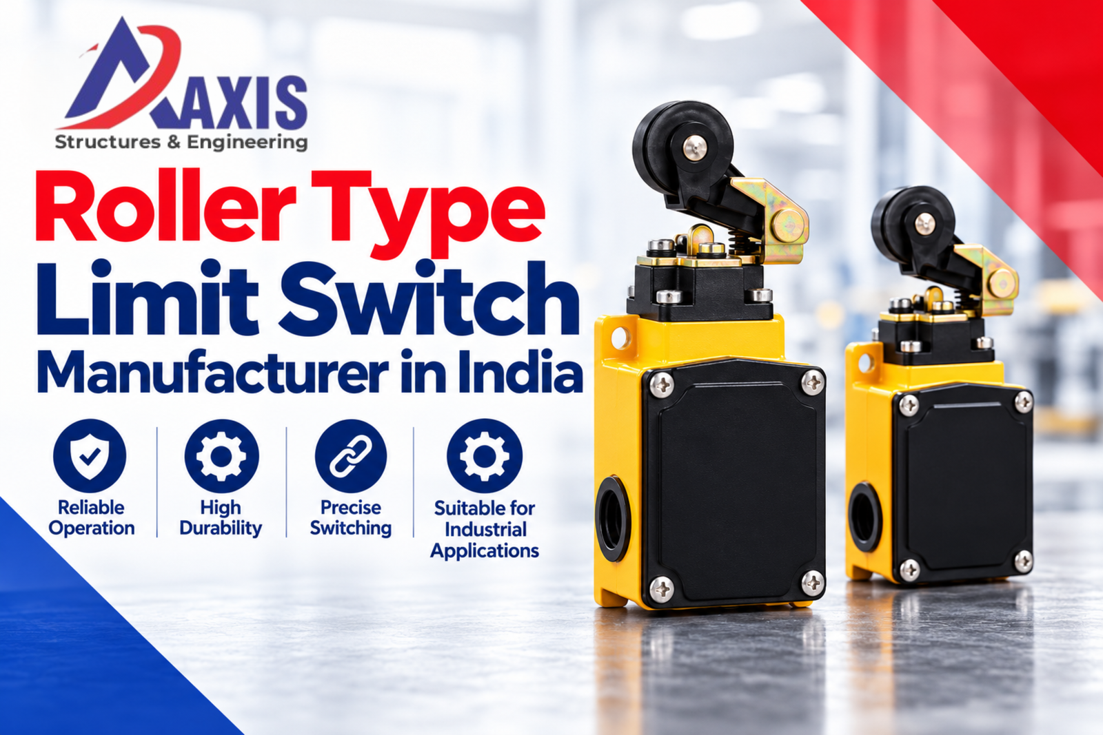
On a crane runway, a travelling trolley may need to slow or stop before it reaches its mechanical end stop. On an automated machine, a moving part may need to signal that it has reached a specific position. A roller type limit switch can provide that physical position signal when the actuator and control circuit are correctly designed.
For buyers looking for a Roller Type Limit Switch Manufacturer in India, Axis Cranes recommends starting with the moving mechanism, not just the switch photograph. Roller orientation, available travel, contact logic and mounting details often decide whether a replacement will work reliably.
What Is a Roller Type Limit Switch?
A roller lever limit switch uses a small rotating roller at its actuator tip to follow a machine cam or moving surface. The cam deflects the lever, and the switch mechanism changes one or more contacts. In a typical control arrangement, those contacts send an input to a PLC or control relay or interrupt a suitable control circuit.
It is a position-detection device, not a load sensor, braking device or mechanical end stop. Whether it is appropriate for a protective stopping function depends on its documented characteristics and the overall safety design.
Why roller actuation is useful
- The rolling contact helps reduce sliding friction where a properly shaped cam engages the actuator.
- A defined actuation position can signal travel limits on suitable crane and trolley mechanisms.
- Contact state can indicate machine position for sequencing and interlocking.
- Side-entry cam arrangements can be practical when straight plunger actuation is inconvenient.
- Actuator travel, alignment and return movement still require careful checking.
How a Roller Type Limit Switch Works
The exact mechanism depends on the model. Most roller lever designs share these functional elements:
1. Roller and actuating lever
A cam, bracket or moving machine part contacts the roller and pushes the lever through its operating angle. Roller material, diameter and permissible approach direction matter. The roller must contact the intended cam surface without a side load beyond the model's limits.
2. Operating shaft and return mechanism
Lever movement transfers through a shaft or mechanism to the switch. Some models offer adjustable lever positions or different head orientations. Return behaviour may depend on the internal spring and actuator design; check the specified release movement rather than assuming every model behaves the same way.
3. NO/NC contacts and switching action
Depending on the product, the switch may include normally open (NO), normally closed (NC) or changeover contacts. Snap-action and slow-action designs are not interchangeable without reviewing the circuit. Confirm the electrical utilisation category and the manufacturer's switching diagram.
4. Housing, terminals and mounting holes
The enclosure holds the contacts and operating mechanism. Mounting pattern, cable entry, sealing and operating environment affect installation. A switch that fits the old bolt holes may still have a different lever pivot or actuation point.
— Suggested quotation for Axis Cranes technical team approval before publication.
Where Are Roller Type Limit Switches Used?
These switches are used wherever controlled mechanical contact can reliably indicate a position. The correct switch and control architecture depend on the application.
- EOT crane bridge travel: detecting a selected position near the end of runway travel with a designed actuator cam.
- Crane trolley cross travel: providing a position signal for travel limitation or sequencing in compatible systems.
- Gantry and Goliath cranes: monitoring suitable movement positions on crane travel mechanisms.
- Conveyors and transfer equipment: confirming a carrier, stop or mechanism has reached a target position.
- Industrial machines: detecting doors, slides, indexing tables or moving assemblies when the actuator geometry permits.
How to Select the Right Roller Type Limit Switch
Start with what actually strikes the roller. Then check the electrical circuit and the available space. A similar-looking replacement may have a different operating point.
Check cam direction, speed and lever travel
Identify whether the cam approaches from the left, right or another permitted direction. Check operating force, pretravel, overtravel and differential travel against the exact product datasheet. The cam must not push the lever beyond its permitted mechanical limit.
Confirm contact configuration and electrical duty
Match the required NO/NC contacts, switching sequence, rated voltage, current and utilisation category. A contact suitable for a control input may not be rated to interrupt a motor directly. Follow the crane or machine's approved wiring design.
Review mounting orientation and repeatability
Compare mounting-hole spacing, actuator head position, lever length and roller location. Confirm that the cam releases the actuator fully after each cycle. Ask for the manufacturer's operating-position and reset details.
Consider dust, water, heat and vibration
Select enclosure protection and materials for the actual workplace. Verify the model-specific IP rating, operating temperature and cable-entry sealing; none should be assumed from the term “roller type”.
Roller Type Limit Switch Specifications to Verify
Specifications vary by manufacturer and model. Before ordering, check the datasheet for these points rather than relying on generic figures:
- Exact switch model and intended equipment application.
- Actuator type: roller lever, adjustable roller lever or another documented design.
- Permitted cam approach direction, lever length and roller dimensions.
- Operating force or torque, pretravel, overtravel and release/differential travel.
- NO/NC contact arrangement, switching action and terminal identification.
- Rated operating voltage, current and applicable utilisation category.
- Enclosure material, ingress protection (IP) rating and ambient temperature.
- Mounting dimensions, cable entry and permissible installation orientation.
- Mechanical/electrical durability data and inspection instructions where published.
- Applicable standards and any required positive-opening characteristic, only where explicitly documented for the exact model.
Practical note: IEC 60947-5-1 is relevant to electromechanical control-circuit devices, but compliance or positive-opening operation must be established from the chosen model's documentation. Do not infer either from a product photo.
Buyer Tips and Common Roller Limit Switch Mistakes
Buyer tip: photograph the switch with its cam
Send a nameplate close-up and one wider image showing the roller, cam path and mounting. That wider view can reveal a wrong approach angle that the switch photograph alone would miss.
Buyer tip: ask for the contact and travel diagrams
Request a terminal diagram and actuation-travel drawing. Two devices can share the same housing outline but have different contact timing and release points.
Common mistake: treating the switch as an end stop
A roller lever must not absorb an impact that belongs to a mechanical stop or buffer. The cam profile, travel speed, braking distance and safety architecture must be engineered separately.
Common mistake: overdriving or side-loading the roller
A misaligned cam can bend the lever, jam the actuator or prevent proper release. Use the permitted approach direction and operating travel from the model instructions.
Common mistake: bypassing a faulty limit input
Do not bridge a switch to keep equipment operating. Isolate the machine in accordance with the site procedure and have a competent technician examine both the switch and its control function before return to service.
Industries Using Roller Lever Limit Switches
Roller-actuated position sensing may be relevant in industrial facilities using cranes, transfer systems or automated machines, including:
- Steel fabrication and metal processing
- Heavy engineering and equipment workshops
- Automotive and component manufacturing
- Warehousing and material-handling operations
- Machine building and assembly lines
- Infrastructure fabrication and maintenance facilities
Roller Type Limit Switch Manufacturer in India — Axis Cranes
Axis Cranes can be contacted about roller type limit switch requirements for crane and industrial equipment applications. The useful starting point is a specification-led enquiry with details of the moving cam, existing switch and control circuit, rather than assuming one roller switch fits every machine.
- Share your existing switch model or nameplate photograph.
- Describe the equipment motion, cam direction and required stopping or sensing point.
- Identify contact configuration, control voltage and switching duty.
- Provide mounting dimensions and environmental conditions.
- Confirm quantity and request model-specific drawings or datasheets.
For replacements, also describe the fault: intermittent switching, broken lever, delayed actuation or failure to reset. Those details help make the enquiry practical.
Frequently Asked Questions — Quick Buyer Answers
What is a roller type limit switch?
A roller type limit switch detects a mechanical position when a moving cam presses its roller lever. The movement operates electrical contacts that signal a control system.
How does a roller lever limit switch work?
A moving part deflects the roller lever to a defined operating point, changing NO/NC contact states. On release, the actuator returns according to the model's mechanism.
Can roller type limit switches be used on EOT cranes?
Yes, appropriately selected roller lever switches can be used for position detection on EOT crane bridge or trolley travel. The installation and control circuit must be engineered for the motion.
What is the difference between roller and plunger limit switches?
A roller lever switch is actuated through a lever and rolling contact, often by a passing cam. A plunger switch is actuated by direct linear depression. Choose based on the cam path and specified travel.
Should I choose NO or NC contacts?
Use the contact arrangement specified by the machine's electrical schematic and risk assessment. Check contact sequencing and rated electrical duty; do not swap NO and NC connections without design approval.
Does a roller limit switch stop a crane automatically?
No. The switch changes an electrical signal. The crane control system must interpret that signal and command stopping; actual stopping distance depends on the drive and brake design.
What should be checked during maintenance?
With the equipment safely isolated, inspect roller rotation, lever damage, cam alignment, housing seals, mounting and terminals. Have a competent person verify contact operation and the overall function using the approved procedure.
What details should I send for a roller limit switch quote?
Share the old model, switch and cam photos, NO/NC requirements, control voltage, mounting dimensions, roller approach direction, environment and required quantity.
Need a Roller Type Limit Switch?
Send your switch model, cam and mounting photos, NO/NC contact requirements, control voltage and quantity to Axis Cranes for a specification-led enquiry.
Send an Enquiry WhatsApp Us


